Bump Mapping
Introduction
Bump mapping is one of the key techniques when building realistic materials. It provides a quick and memory efficient way of adding fine detail to surfaces.
A traditional way to define a bump map is using a bitmap image to define the bumps: the brighter the color, the higher the bump. The major advantage of this approach is that the user can define the shape of bumps by drawing, which is intuitive. Disadvantages include high memory usage, finite resolution and the regular grid-like nature of the bumps.
Bumps can also be defined 'procedurally' using VSL objects such as 'Noise' or 'Wave'. This method is suitable for representing various semi-regular real world surfaces, such as skin of a reptile, surface of a rock, waves on water, etc. Procedural bumps can have very high accuracy (= level of detail), and they do not require much computer memory.
Realsoft 3D provides two different solutions for bump mapping:
- Modifications of the 'Bump height' channel in the 'Surface geometry' shader
- Direct modifications of the 'Bump normal' channel in the 'Surface properties' shader
The first alternative is a general method and suitable for all kinds of bump mapping situations. Direct 'Bump normal' modifications are more limited but are usually faster to compute. Both approaches are considered below in more detail.
Using the Bump height channel in a Surface geometry shader
This is the recommended bump mapping method because of its generality. The examples below show the structure of image based and procedural bump maps.
Image bump map

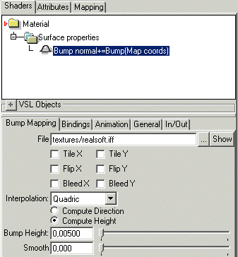
The 'Bump' VSL object can be used for computing bump height values from a bitmap.
The 'Texture' object is not continuous enough for smooth bumps.
Notes:
- Select 'Cubic' interpolation for smooth bumps, or apply 'Smooth' filter for even greater smoothing.
- The 'Compute height' option should be set.
- Use the += operation to add new bumps to previous ones (to change this go to
the General tab).
- Do not 'General/Normalize' the bump height channel (see General tab).
Example file: Materials/Image Maps/Bump Map
Procedural bump map


The image above shows a simple procedural bump map. The height of the bumps can be adjusted using the 'Amplitude' control of the Noise object.
Notes:
- Bump height units are measured in meters. Therefore, height values are typically
very small, from 0.001 to 0.01 (1 mm - 1 cm).
- The computed Bump height value should be added to the previous value (+= operation). This ensures that several bump maps can be combined without problems.
Example: Default material library/Wrinkled
Using the Bump normal channel in a Surface properties shader
Image bump map
The VSL structure of a typical image bump map:

Notes:
- The mapping geometry should match the shape of the target object: spherical mapping is suitable for a sphere, cylinder mapping for a cylinder, parallel mapping for a planar surface and default UV mapping for a freeform Nurbs surface. This method cannot be used for complex SDS shapes.
- General/Normalize option of the Bump operator should be set because the surface normal is needed in a unit form.
- 'General/Transform to material space' option of the Bump object should be set so that the normal is modified in a mapping space relative way
Example file: tutorprojects/material/vsl/pixelbump
Procedural bump map
The VSL structure of a typical mathematical bump map is:

Notes:
- General/Normalize should be set.
- The noise should be centered on zero: set Noise/Base to -h and Noise/Amplitude to 2*h, where h is the magnitude of noise (for example 0.1).
- General/Transform to material space option is not necessary, because noise is similar in all directions. However, if the bump procedure defines regular shaped bumps, which should follow the target surface, the transform option should be set and the mapping geometry and surface geometry should match.
- The Noise operator works best with a parallel mapping, because the computed
coordinates are continuous. Spherical mapping renders with a visible seam.
Example file: tutorprojects/material/vsl/mathbump
Curve operator bumps
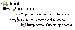
The 'Derive' object can be used to transform an arbitrary VSL object to a bump map suitable form. For example, one can draw the shape of bumps using the curve operator:

Notes:
The first VSL object in 'Surface properties' shader is 'Operation/Modulo by 1'. This object computes repeating sequence of 0..1 coordinates and hence creates tiling of the bump pattern. The 'Curve' object needs not have 'Normalize' or 'Transform to mat space' set, because the 'Derive' object does this. Bump height can be adjusted by modifying the vertical scale of the curve. Bump map operates on two-dimensional surfaces, and therefore the third curve is unused. The first (red) curve controls bump height in the horizontal direction, the second (green) curve controls bumps vertically. Objects such as 'Noise' or 'Random' do not require use of a 'Derive' object, because 'Derive' processed noise is just another noise field and the same applies to 'Random' as well.
Example file: tutorprojects/material/vsl/curvebump
Bump map and shadows
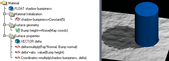
An additional level of realism can be obtained by distorting the shadows on a bumped surface. The material below shows how to achieve this:

A shadow on a bumpy surface
Notes:
- The 'Material initialization' shader is used to initialize the variable defining the amount of shadow distortion.
- Surface geometry computes the bump map in the usual manner.
- In the Surface properties shader, the surface point is moved the amount defined by Bump height channel to the direction of the surface normal. This affects the illumination and shadow computations, which will take place later. Some extra care is taken to move the point to the camera side of the surface, not behind it. Moving the point behind the original surface would make the surface cast a shadow onto itself.
Example file: tutorprojects/material/vsl/bumpyshadows
